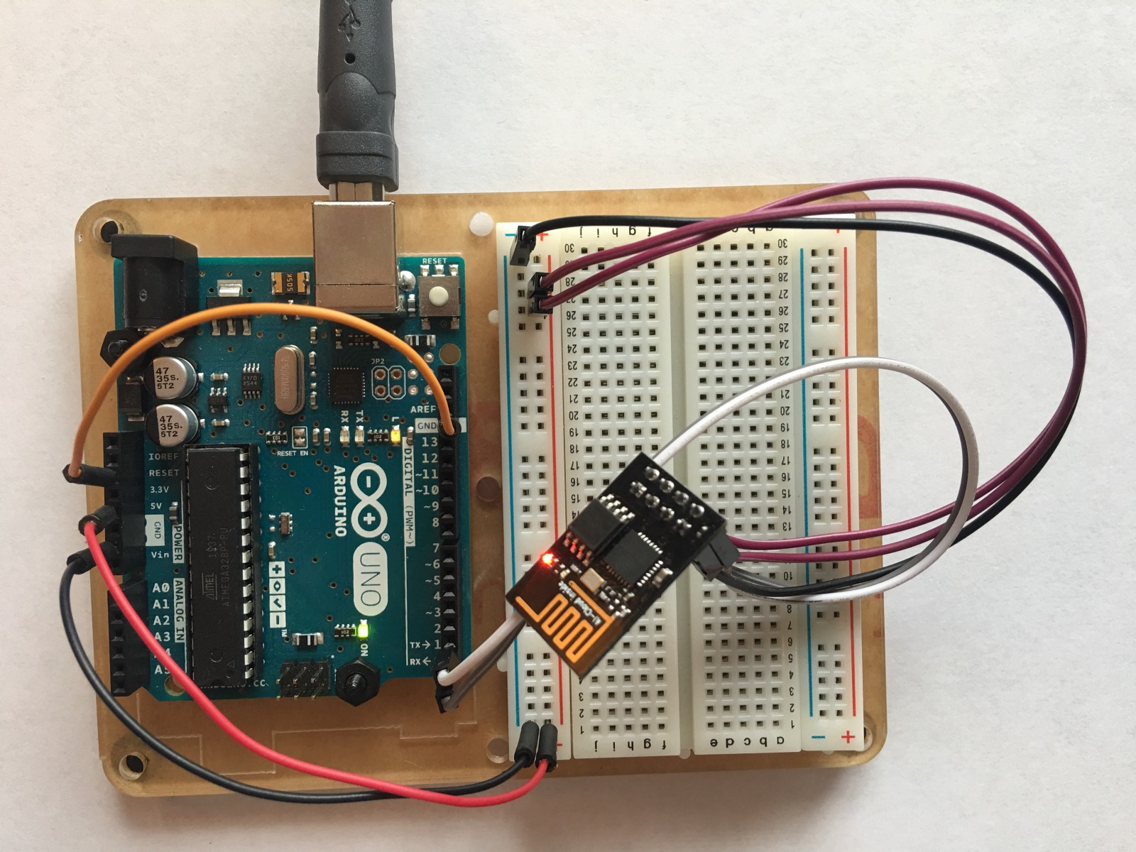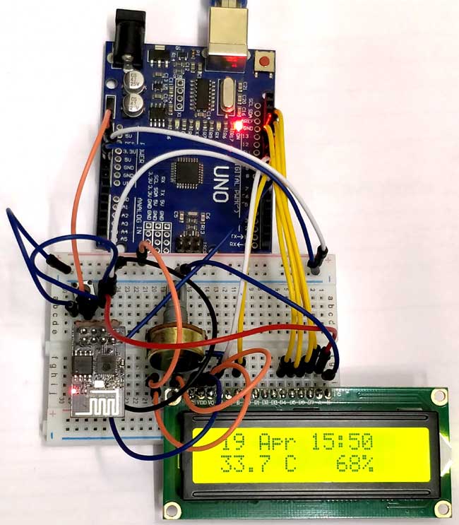

It should display the IP address of your local webserver.
SOFTWARE SERIAL ESP8266 PROGRAMMING SOFTWARE
Then, in the loop section, we store AT commands in strings so that we can send them via Software Serial. Using InitWifiModule(), connect to your WiFi network. Then, in the setup section, initialize the serial monitor and serial communications with your ESP8266’s baud rate.

To avoid having corrupted data, we transfer serial communication with the ESP-01 to pins 2 and 3. The default pins for serial communication, 0 and 1, tend to get busy when the serial monitor is running. SendData("AT+CIPSERVER=1,80\r\n", 1500, DEBUG) įirst, initialize a SoftwareSerial communication line. Using the Software Serial library we can send serial commands to Arduino and Arduino with again send it to ESP8266 and vice. 1.Using Arduino as Host MCU to communicate with ESP8266. SendData("AT+CIPMUX=1\r\n", 1500, DEBUG)

CodeĬloseCommand+=connectionId // append connection id Plug and play! All you need to do is set the board in the Arduino IDE to NodeMCU. In the Arduino IDE, choose Generic ESP8266 Module. connect the pin 0 to GND to start program mode. Connect the EN/CH-PD (Enable) pin to the 3.3V supply. Then, create a voltage divider just like before. Using the Arduino to program the ESP-01įirst, to set the Arduino board as an ESP programmer, connect the RESET pin to GROUND.

SOFTWARE SERIAL ESP8266 PROGRAMMING CODE
Let’s use them on actual Arduino code in the next section. To check the current mode the ESP8266 is in, use AT+CWMODE?.īut they have their limits. To set as an access point, enter AT+CWMODE=2. To set the module as a station, enter AT+CWMODE=1. Fundamental AT commandsĪs mentioned in the previous article, the ESP8266 can be set to 3 different modes. Set the baud rate to 115200 and enter the desired AT command. In the Arduino IDE, choose Generic ESP8266 Module as your board of choice. To prevent this, we use a logic level converter or a voltage divider to reduce the signal to 3.3V. Although the ESP8266-01’s TX and RX pin are 5V tolerant, it still gets damage in the long run. The default logic level of an Arduino is 5V. Sending AT commands using Arduino UNOįirst, create a voltage divider using a 1kΩ and 2.2kΩ resistor. They can either be sent using the serial monitor or via the ESP8266 sketch. I also try to implement code with AltSoftSerial but I have library issues - my laptop does not recognize it (I downloaded it and I put it in the same folder with my code).Further, AT commands are often used for rapid testing of the ESP8266. Also when I try to upload my program to the Arduino board, I have to disconnect the ESP. So with that problem I can't send or receive any command to/from the IDE. The problem I had and I can't handle is that when I start up the Arduino Tx and Rx LEDs work continuously so I can't have access to my serial monitor of the Arduino IDE. The 5V Arduino will read 3.3V as HIGH so you can connect the ESP8266 TX pin directly to the Arduino RX pin. You only need the voltage divider on the Arduino TX pin.


 0 kommentar(er)
